Reflectance Calibration with Phantom 4M Multispectral data (Updated 14-05-2021)
Last Update: 14.5.2021
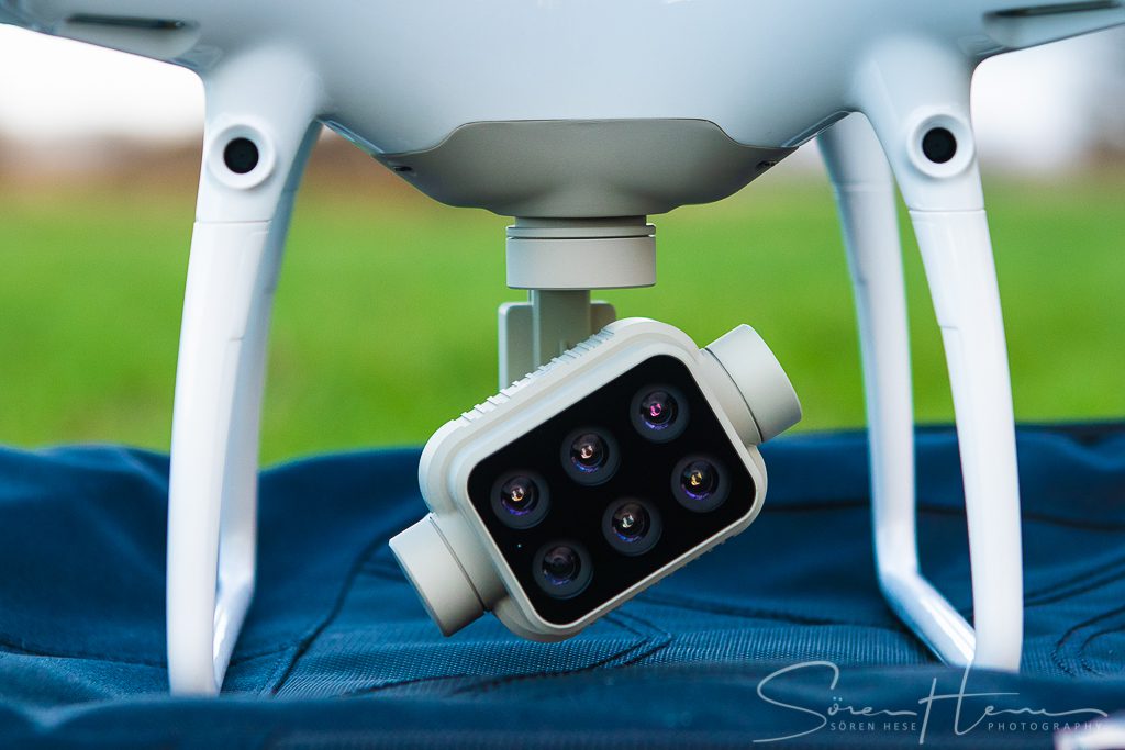
There was some confusion in the past on how to process the Phantom 4M Multispectral data to “reflectance” level. Here a short summary for Agisoft Metashape 1.7.2 with a 50% reflectance panel from Micasense (update: now its from SphereOptics).
In general: 1. the P4M sun illu. sensor works for normalizing the within flight campaign variations while 2. the panel reflectance measurement is used to make different multispectral data measurements from different campaigns comparable by converting DNs to reflectance.
Since vegetation surfaces do not fully reflect light in lambertian style this does not always fully work, but we can get close when the illumination directions of the different flight campaigns are comparable and when relative change is needed. Although … reflectance calculation is usually done to get a value for absolute comparison of spectral information with reflectance spectra or other datasets.
The Agisoft Metashape Workflow (1.7.2):
- Import all Geotiff folders with the multispectral tiff files. Choose “Add Photos” as “Multi-camera system”. Agisoft will not use the RGB Jpegs by default but you could create an additional “Chunk” for the RGB data and merge the products later.
- Locate the reflectance panel tiffs using “Tools-> Calibrate Reflectance”. Locate the panel files automatically or move the panel tiffs manually into a Group Folder under “Cameras” and rename the folder to “Calibration images”. For each channel insert the right reflectance values (0.518 f.e.) that are specific for your panel and your band setup in the”Calibration Reflectance” tool. (Micasense Rededge band specs are close to P4M camera specs but not identical so using the RE values with a Micasense panel should work somehow but here more accurate values might be needed. The reflectance is not changing much with different bandwidth however – so this can be neglected with professional calibration targets and is likely buried in other uncertainties). In general the sun sensor can be deactivated when the flight was fully sunny, but should be activated when illum. changes. For longer flights with multiple battery changes I usually keep this ticked (but panel measurements between flights is suggested). Ok the “reflectance calibration” and
- check that masking of the calibration area of your panels is selected (the rest of the image area within the calibration panel tiffs should be masked out – darker) in every channel (change channel under “Tools->Set primary channel” to check the mask for all channels). If this doesnt work automatically you have to choose the selection tool and use “add to selection” and “invert mask” – not a very logical workflow but the panel area should than be (extra) brighter than the rest of the image. Put this image into a group named “Calibration images”. Important: the name of the Group has to be “Calibration images” otherwise the “Calibrate Reflectance”-tool will not find the panel image in manual mode later!
- If masking and “Calibration images” folder was set up manually make sure you deactivated the calibration image to avoid an alignment of the calibration image.
- Increase brightness levels (Tools-> Set Brightness) to about 600% (only for visualization).
- Set “Tools->Primary Channel” to NIR or RE if you work with vegetation surfaces. Primary Channel is used for matching.
- Proceed with workflow processing:
- Align all tiffs using your preferred setup (High/80000/8000/AdaptiveCameramodelFit no – if camera meta data should be used – see preferences),
- Build Dense Cloud (Ultra High, no filtering, can be reduced to depth maps only if DEM is to be derived from depth maps),
- Build DEM (quality: ultra high, UTMxy N ETRS89 …, build from dense cloud),
- Build Ortho Mosaic
- Check that “Tools->Camera Calibration” shows a tick at “Bands-> normalize band sensitivity”.
- Under “Tools->Raster Transform” do a normalization of 16uint to 0-1 reflectance using “Input Band” B1 -> B1/32768 and repeat for all other channels. This is important for the back-scaling into unscaled reflectance. Agisoft scales 100% reflectance to the middle of the 16Bit space: 65536/2 = 32768 and this follows basically the Micasense recommendation and processing guidelines in Atlas Cloud . https://support.micasense.com/hc/en-us/articles/215460518-What-are-the-units-of-the-Atlas-GeoTIFF-output-?mobile_site=false
- Export the Orthomosaik using “Export to Tiff” with the “index value” option under “Raster transform”! Now check the TIF file – it should show 32R Bit values between 0 and 1 for all channels.
- Optional: if you like you could add the P4R DSM by importing it to your workspace (if you happen to have this dataset avail. : )). Extra high res DSM info is usually only increasing the ortho correction artifacts in P4M multispectral data – if you are working with non-continuous surface types but there are applications where this could be a lot of help.
–
Overall this seems to work. However there are some indications from my initial testing in March 2021 that repeated flights under the same conditions do not lead to comparable reflectance values. Here some more testing is clearly needed with reference panels in the field. I measured up to 20% reflectance change after remapping a few days later and this is not related to vegetation change. Its difficult to assess where these changes come from. There might be some illumination changes at work here since some TIFs where captured under overcast conditions and the two flight campaigns did not take place at the same time of the day. I removed these from the TOP mosaicing and reflectance calibration process. NDVI calculations however seem to be very comparable and show expected (locally with ground reference confirmed) regreening change effects. Differences between the NDVI calculations on likely unchanged surfaces never exceed the 0.02 range. Some comments on the Agisoft Support pages also hint towards the vignetting correction in Agisoft Metashape that might have an effect on the reflectance calibration. More test flights under comparable conditions are needed.
Note: reflectance also changes with modified illumination geometry from different flight path patterns and flying height ( Stow, D.; Nichol, C.J.; Wade, T.; Assmann, J.J.; Simpson, G.; Helfter, C. Illumination Geometry and Flying Height Influence Surface Reflectance and NDVI Derived from Multispectral UAS Imagery. Drones2019, 3, 55. https://doi.org/10.3390/drones3030055 ). This must be clearly taken into account when flights are planned with varying daytime and/or different flight pattern orientations.
To create the best possible reflectance results the panel calibration should be repeated with every battery change. Processing should than be done on flights and TrueOrtho mosaics should later be combined to one mosaic imo.
Parts of this information was summarized by Agisoft here: https://agisoft.freshdesk.com/support/solutions/articles/31000148780-micasense-rededge-mx-processing-workflow-including-reflectance-calibration-in-agisoft-metashape-pro . This tutorial describes processing for MicaSense RedEdge MX data but it was also suggested by Agisoft Support for P4M data.
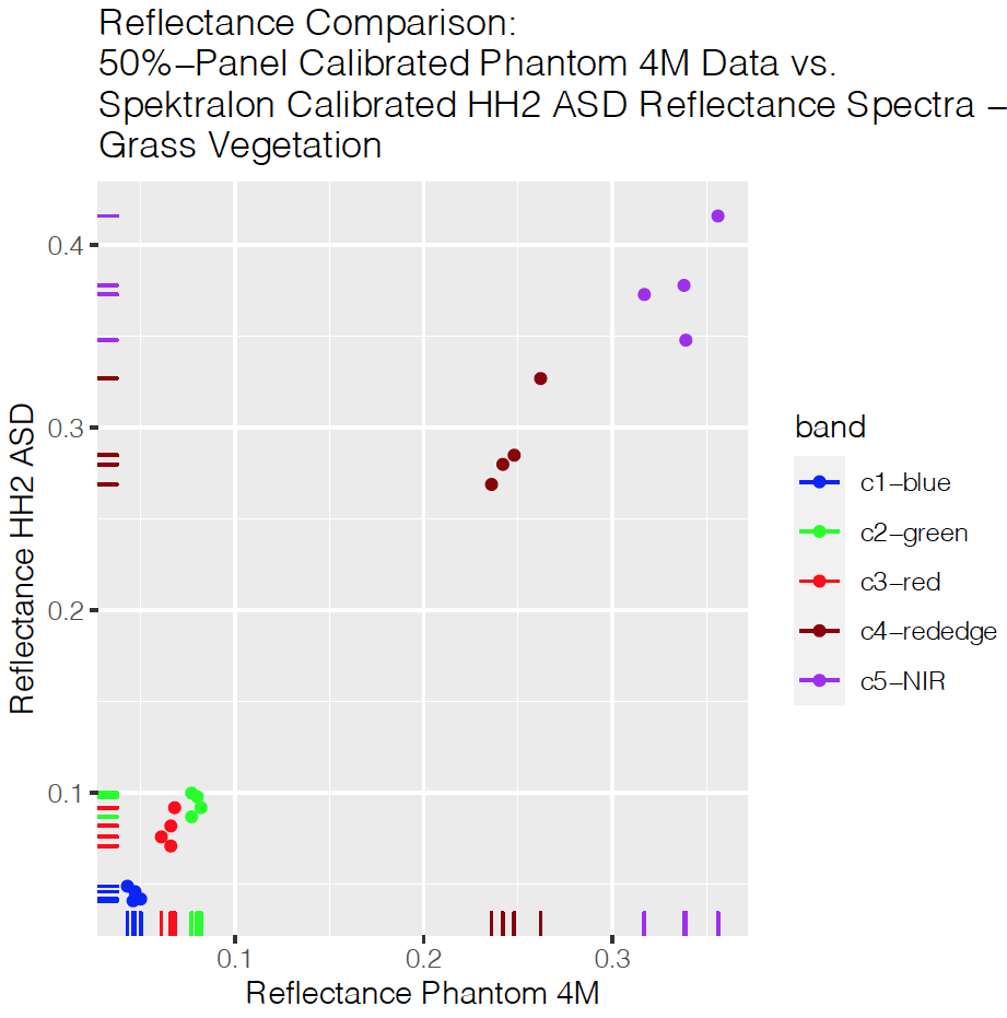
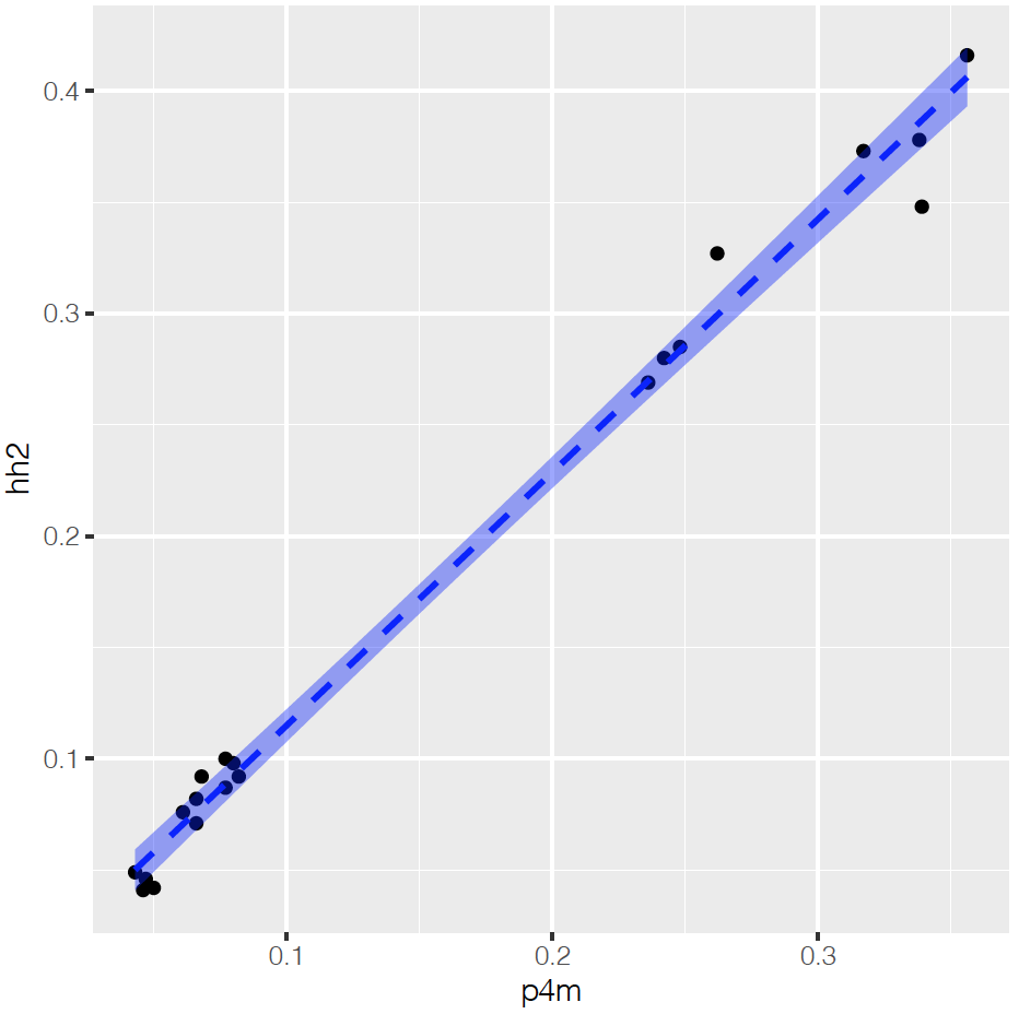
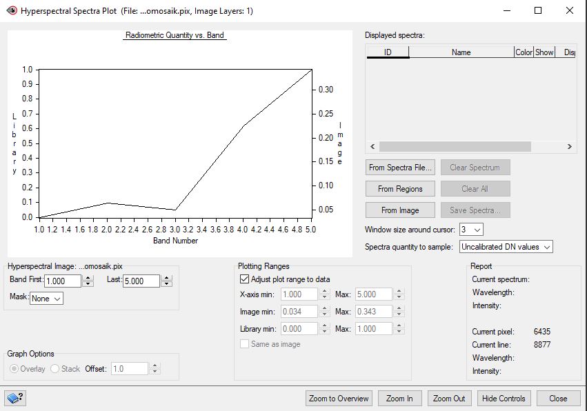
UPDATE 21.04.2021: we measured vegetated grass surface reflectance with a HandHeld2 half-range spectro-radiometer from ASD (Spectralon WR normalized) and compared these reflectance values with the finale P4M reflectance values after Metashape processing to TrueOrthoPhoto (TOP) level with 3×3 pixels. The figure below clearly shows that the reflectance difference between HH2 measurements and P4M measured values is below 5% reflectance (for grass surfaces). The flight data was captured only minutes after calibration with a 50% reflectance panel and atmospheric conditions were stable.
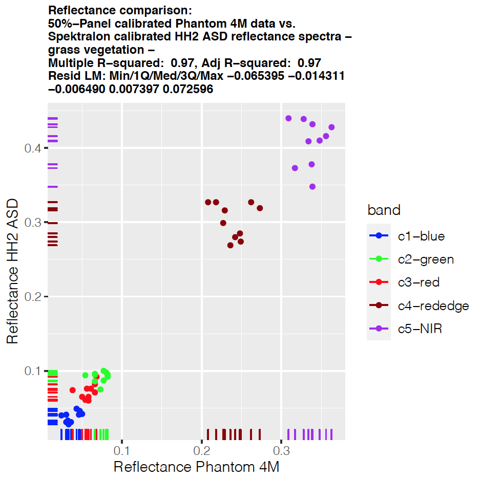
UPDATE 14.05.2021: Another vegetated grass surface reflectance measurement mid of May clearly revealed more variability. Here the P4M ortho processed mosaic strongly underestimated the reflectance that we measured with the ASD HH2. Conditions have been very different compared to April. 28°C and noticeably haze was covering the sun occasionally. So overall these differences are likely linked to atmospheric variability and not to data acquisition and/or data processing issues.


Do you happen to use the standard multispectral image collection parameters recommended by DJI in their YouTube tutorial?
https://www.youtube.com/watch?v=PWRafL6wXew
Multispectral:
AE – Unlocked
Average Metering (not Center-weighted average metering)
Camera – Auto Mode
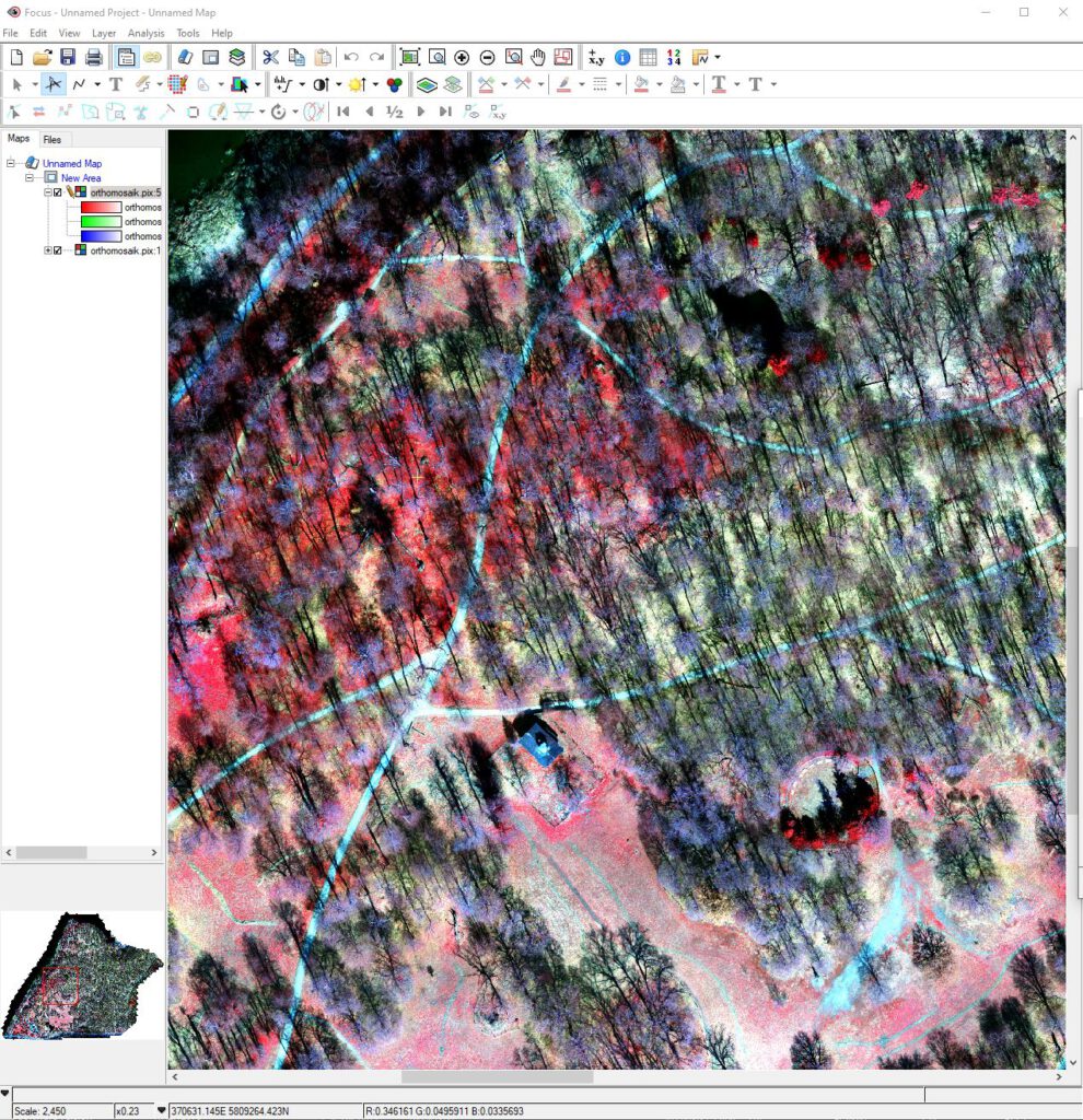
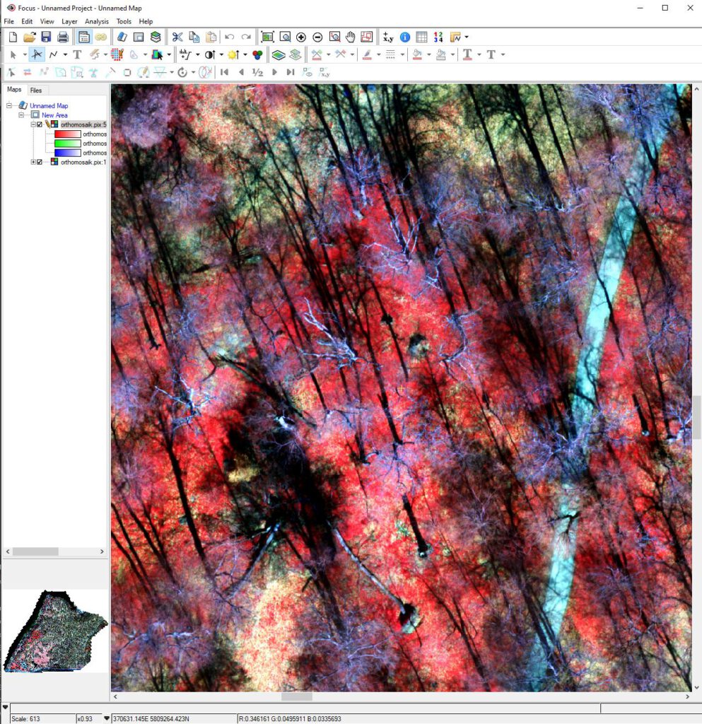
If so, do you observe a circular “hot-spot” effect that looks almost like vignetting, particularly in the NIR TIFF images? I cannot determine the cause or how to resolve it with our P4 Multispectral.
Thanks,
TPC