Micasense Altum-PT Data Capturing and Processing – the Park3D Project

Another report from the Park3D project in cooperation with SPSG (Stiftung Preußische Schlösser & Gärten).
Using multispectral cameras on UAV platforms has been not so straight forward in the past and the situation hasn’t changed much. If you are used to the Mavic 3 Multispectral RTK or the Phantom 4 Multispectral RTK systems than the integrated way how DJI managed to combine the camera system with flight planning is something that somewhat spoiled us – DJI Ground Station Pro and DJI Pilot work nicely with these multispectral systems. The moment you step into the world of external non-DJI /not-so-integrated cameras things get more complicated – in a way we are back to how things were before firms like DJI integrated camera systems so user friendly that the RC model nerd was not needed anymore to get things up in the air flying and reliably taking data … .
The Micasense Altum-PT is however much easier to integrated than those TetraCam systems or the like 20 years ago – thxs to the Skyport that is directly mounted on the Altum-PT and easier in camera setup customization / faster interfaces.
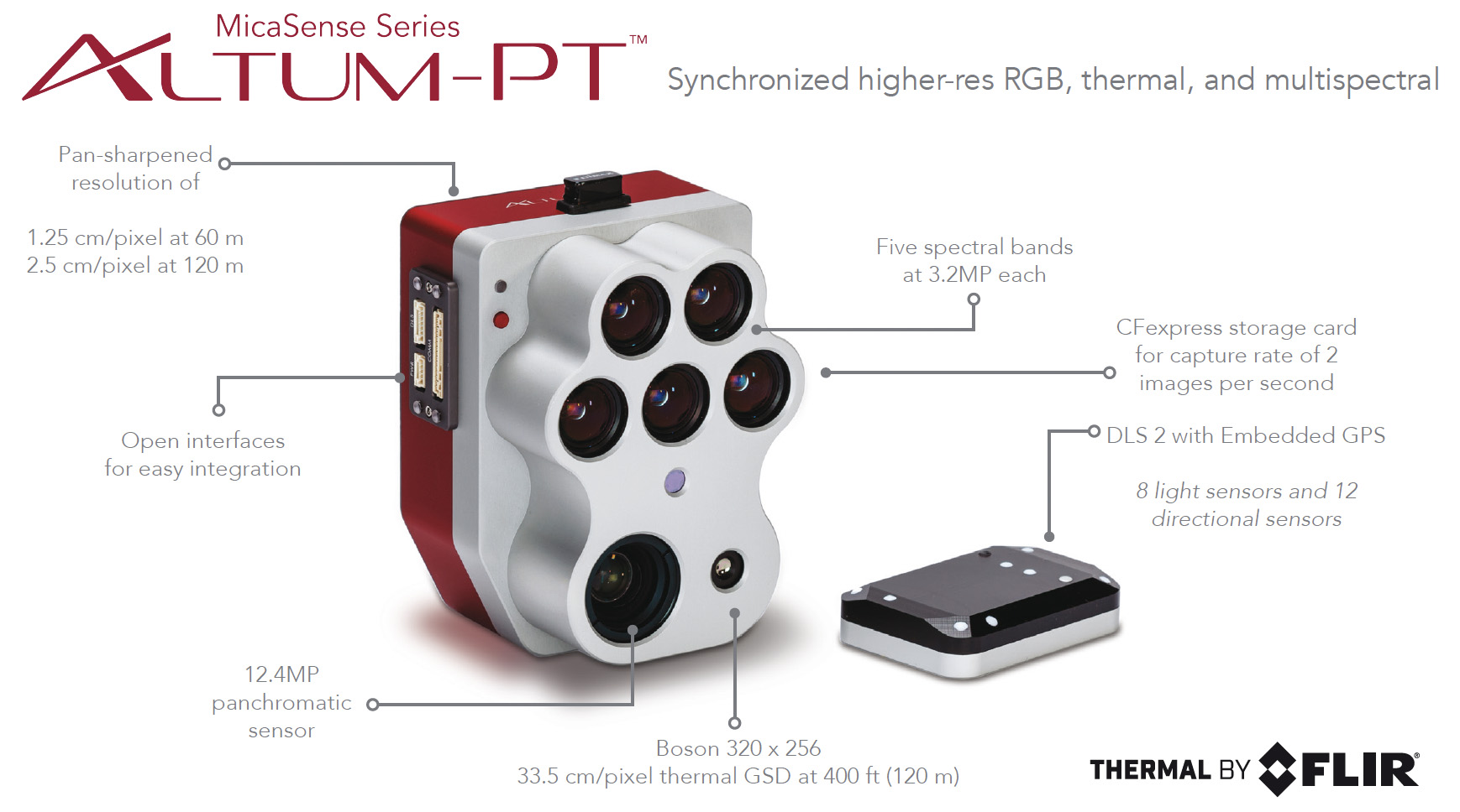
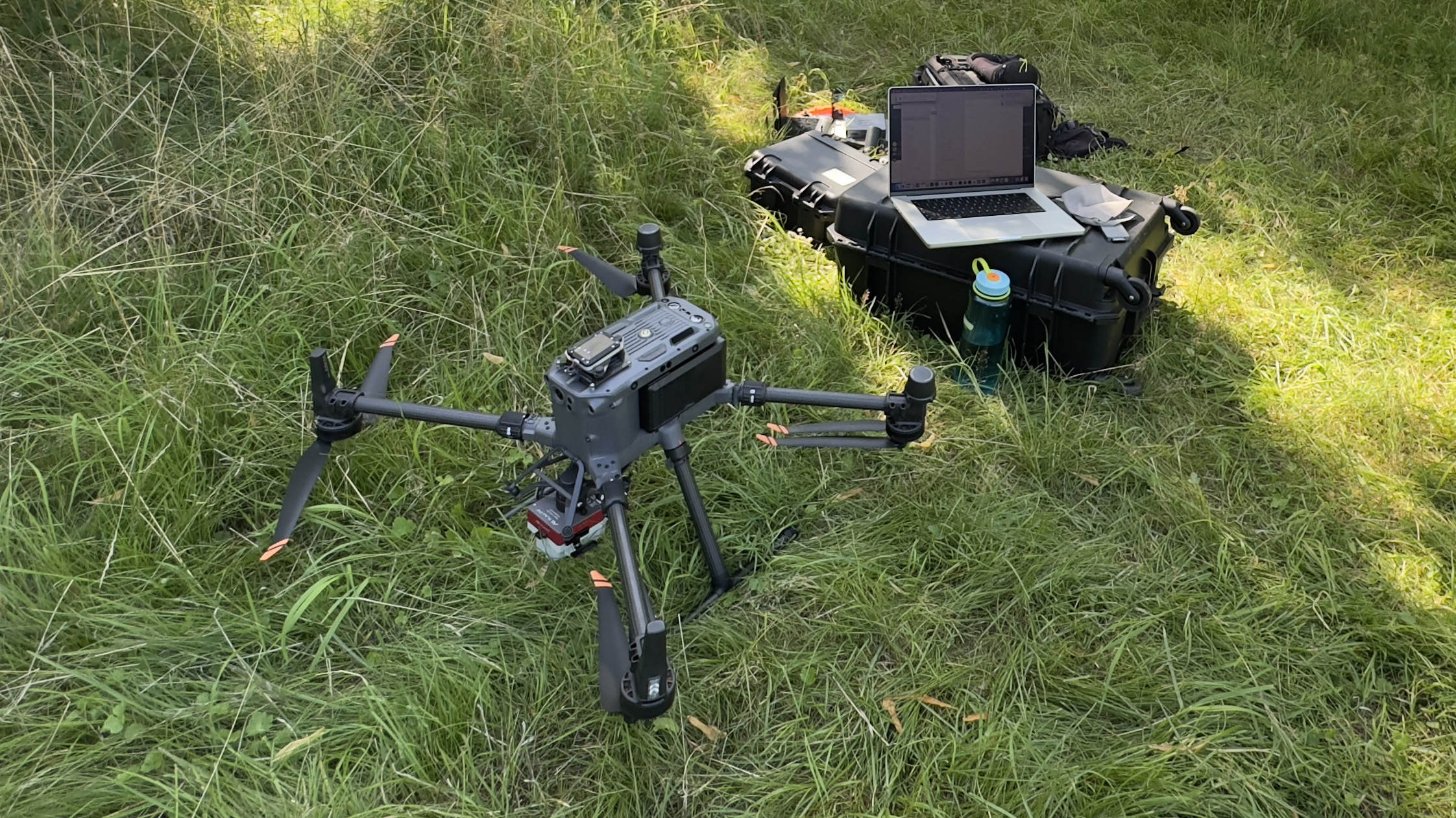
Fig. 2: Altum-PT mounted with the Skyport and with DLS2 installed on top of the DJI M350 RTK – configuration without FTS (Flight Termination System).
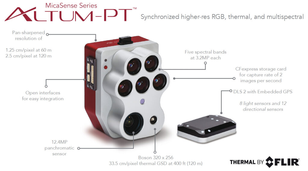
However when you start flying with the Altum-PT or other Micasense multispectral camera systems you quickly realize that things are getting difficult or at least complicated both in terms of flight planning and in terms of camera setup. Integrating the Altum-PT with the DJI Matrice M350 RTK (and the M400) you can use the available integration kit – namely the DJI Skyport adapter. Most of the users buy the Altum-PT already preconfigured with the Skyport adapter. With this adapter you can mount the Altum-PT directly on the M350 but you will not see any image preview or a control image from the Altum on your M350 Remote Control. However the DJI Pilot 2 App allows defining a camera setup with all camera specs that are needed to create a full flight plan with a non-DJI camera. You define a new camera by inserting camera name, image size in width and height and sensor site in width and height and focal length. For the Altum you would choose the multispectral channel specs. You find a detailed instruction on the MicaSense Knowledge base webpage under:
https://support.micasense.com/hc/en-us/articles/360023136753-DJI-Pilot-and-MicaSense-Sensors
The camera setup lists standard multispectral sub cameras with: 8 mm (blue, green , red, red edge, NIR (2064×1544), 16.6 mm (pan) (4112×3008), 4.5 mm focal length, thermal camera LWIR (320×256). Field of View (VGOV) is comparable for all sensors at 48° HFOV x 36,8°
This is very handy because the flight planning can be directly done within your Pilot 2 app and you dont have to import from an external flight plan software. Where it gets a bit tricky is when you want to control the camera in flight.
You can preconfigured the camera via Wifi to start capturing images in all channels or in a channel subsection
1. when the M350 reaches a certain flight altitude or
2. when a specific overlap percentage is detected by the GNSS sensor of the DLS2 or
3. when the DJI controller triggers the camera via Skyport from within the flight plan data and the configured overlap in the flight plan.
For option 3 you have to deactivate the in-camera auto-trigger of the Altum-PT. If you don’t than the DJI Pilot 2 App will additionally trigger the camera at 1 Hz and you end up with approx. two times the number of pictures as anticipated. This makes things very complicated in data processing because its difficult to remove every second or third image from the flight later AND keeping the exact overlap schema intact. The DJI Pilot 2 App will always show the actual image count as a control instance but it will not account for shots done by the auto-trigger routine of the Altum-PT – so eventually you run into a card full error when the DJI controller cannot anymore trigger the camera and the image counter just stops. So its best imo to deactivate the auto-capture function of the Altum and to just let the “Pilot 2” App do the capturing on the M350 – likely its the same with the M400.
The Altum-PT writes to card like hell and even manages to shoot 2 image sets per second in TIFF 16 Bit file format. Since the thermal images are always captured in TIFF 16Bit I would always also capture the other channels in TIFF 16 Bit (optional also DNG format is available). The sensor writes 12 Bit – so you loose some card space but I find it easier to not have to handle the DNGs (optional RAW format) in post additionally to tiffs. Both formats are lossless. This quickly fills card space. I had no problems with the delivered Sandisc Extreme Pro CFExpress 128 GB card from Micasense but with the Sandisc Extreme Pro 512 GB version the camera just stopped writing to card in one of my flights and I followed all recommendations (format in camera to vfat etc). So that is something to keep an eye on.
A bit annoying is that you have to connect to the camera WiFi to format the card when you offloaded all images and when you prepare for the next flight, especially when your iphone is running as a router for the SAPOS RTK signal you do not want to change to the Altum WiFi – so having additional CFE cards is easiest in the field. Just swap the cards and start the flight plan again.
Altum-PT multispectral data processing is done with calibration panel images that were captured on the ground between the different flights within one campaign (not needed if you only want thermal data). This is easiest done with the small trigger on the camera itself – the DLS2 will light up a blue LED when capturing an image dataset was successful. Be careful not to cover the DLS or to overshadow the reference panel when you trigger the camera for panel images. The sun illumination sensor needs to capture correct values for the data calibration to reflectance later.
The DLS2 (downwelling light sensor) is used to measure the ambient light and sun angle and writes the data to the metadata of each TIff image captured. This measurment can later be used to correct for global lighting changes in the middle of a flight (f.e. due to clouds). Additionally DLS2 provides GNSS data. When connected via Skyport the triggering and GNSS comes from the Drone directly. Micasense suggests not to use the irradiance data for correction when the conditions are comparable constant. I also got a bit hesitant to use the sun illumination correction – I had various flight campaigns under constant sunny conditions where the sun illuminated correction introduced artefacts in the resulting true ortho mosaic later.
In Metashape you import all files using the multi-camera import option, you run the panel file auto detection routine and within the “Calibrate reflectance” setup you insert the reflectance values for the panel surface in the various channels (usually something between 0.49 and 0.51). The thermal channel has no reflectance calibration value. This channel is already pre-calibrated and in raster transform you just recalculate using this simple formula: (B7/100)-273,15 to get first to Kelvin and by subtracting 273 you get °C values. The thermal camera did in flight calibration (this could lead to gaps in the full true ortho thermal image mosaic occasionally) and is preconfigured for the emissivity of 1.0. The multispectral channels are transformed by dividing through half of the 16 Bit space (f.e. B1/32768). The full processing workflow is also documented here: https://agisoft.freshdesk.com/support/solutions/articles/31000148381-micasense-altum-processing-workflow-including-reflectance-calibration-in-agisoft-metashape-professi

Fig. 3: Channel “Raster Transform” – calculator setup in Metashape 2.2.2.
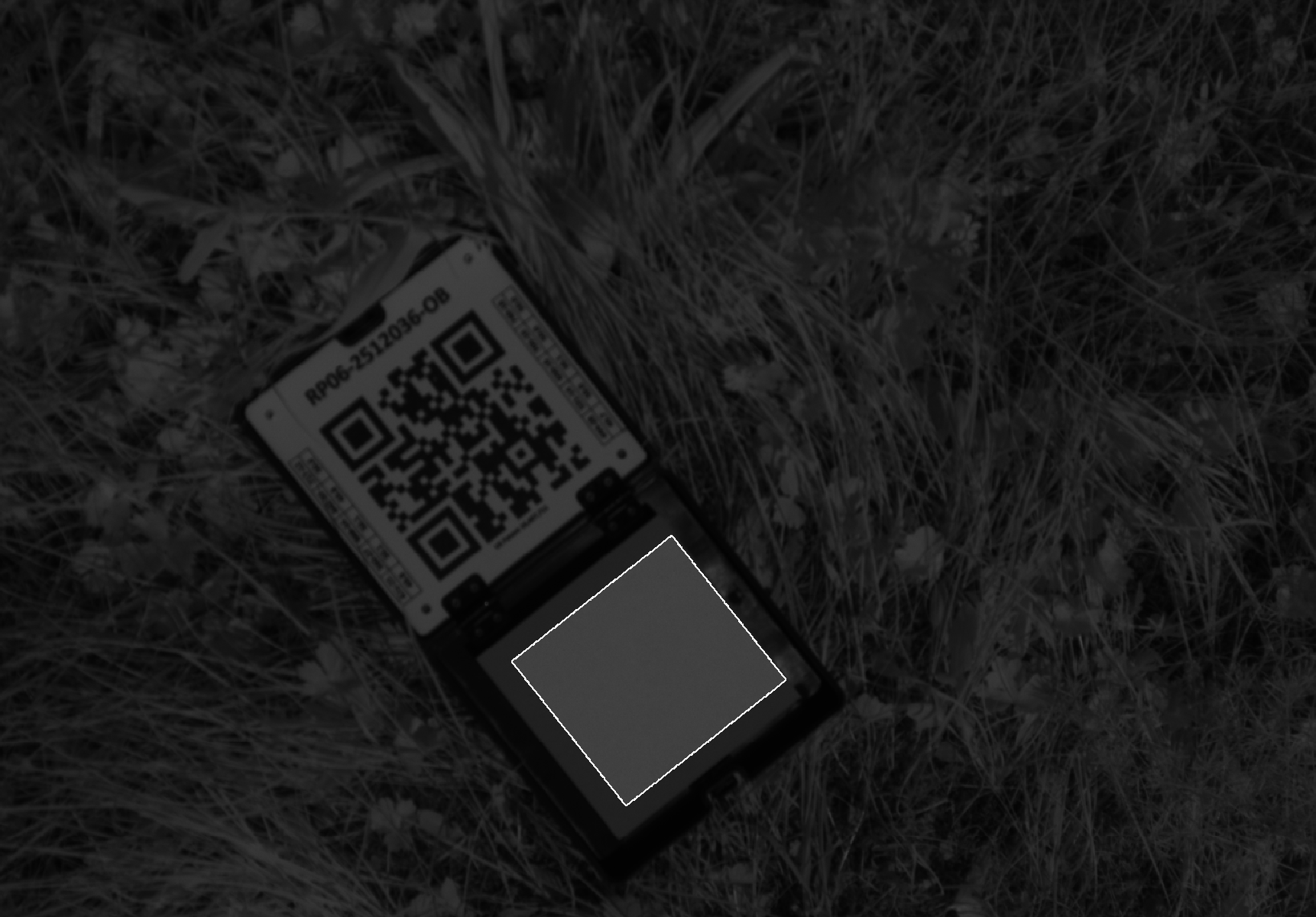
Fig. 4: Panel image with masking of non-panel areas – here the area was automatically detected by Metashape and the file was automatically move to a calibration file group.
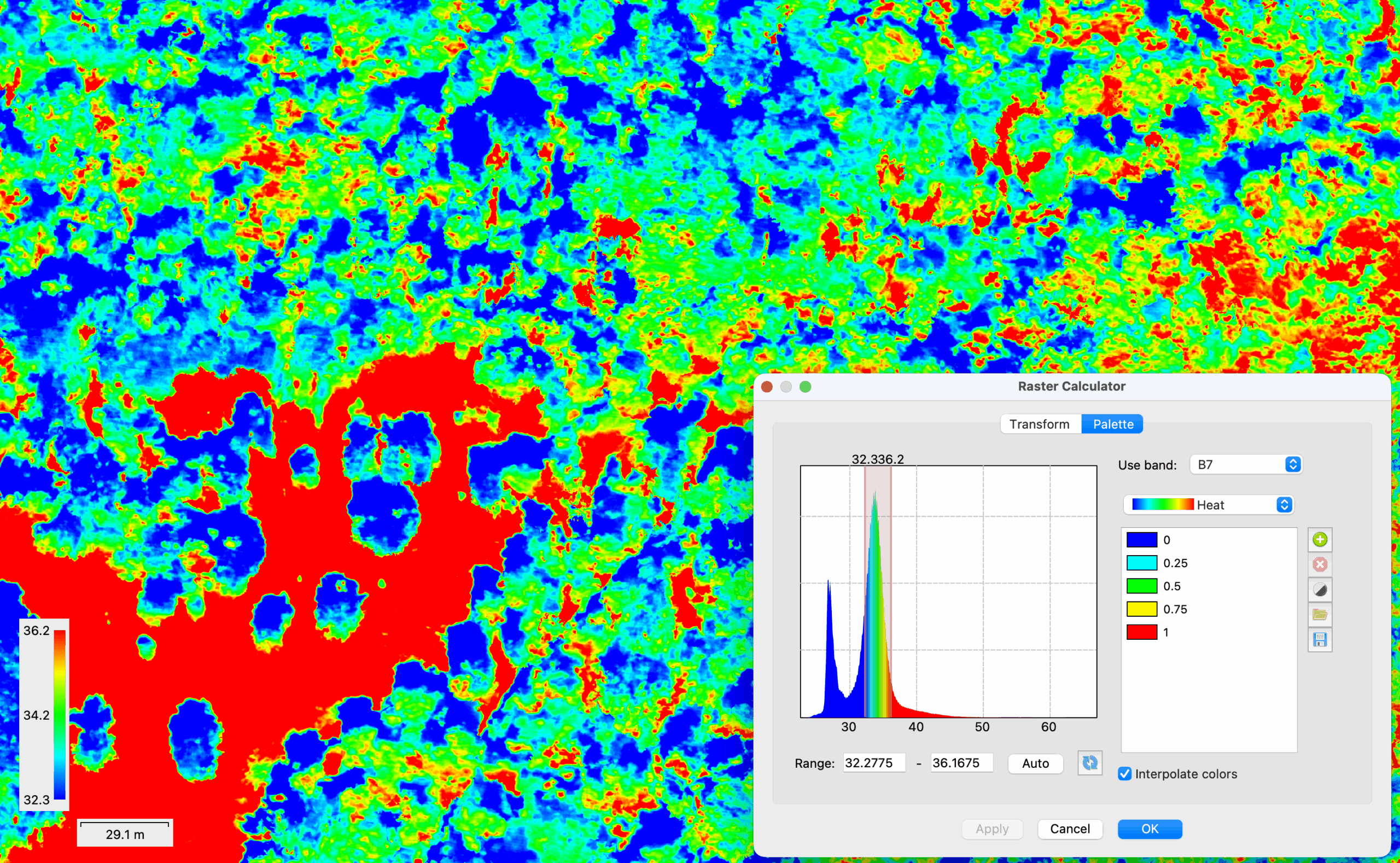
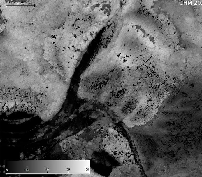
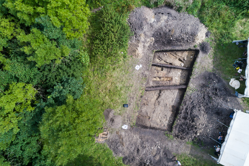
Fig.: 5: Thermal true ortho mosaic of forested area with temperature values between 32 and 36 °C color coded in the Palette section of the “Raster Transform” function in Metashape 2.2.2 (captured at 2 PM in August 2025, air temperature was at 33°C).
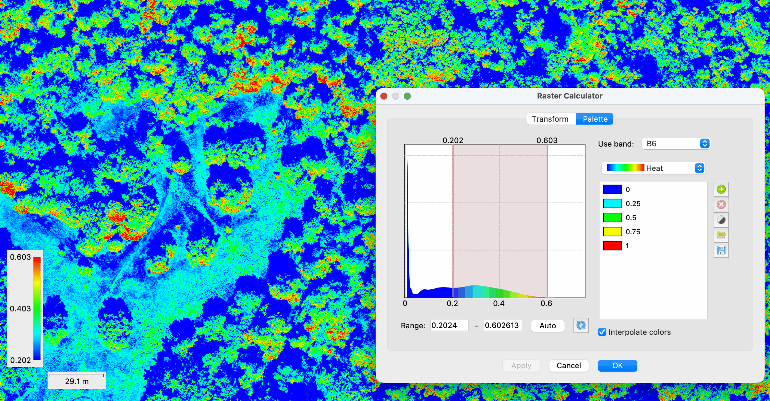
Fig.: 6: NIR channel – true ortho mosaic with reflectance values between 20 and 60 % – color coded in the “Palette” section of the “Raster Transform” function.
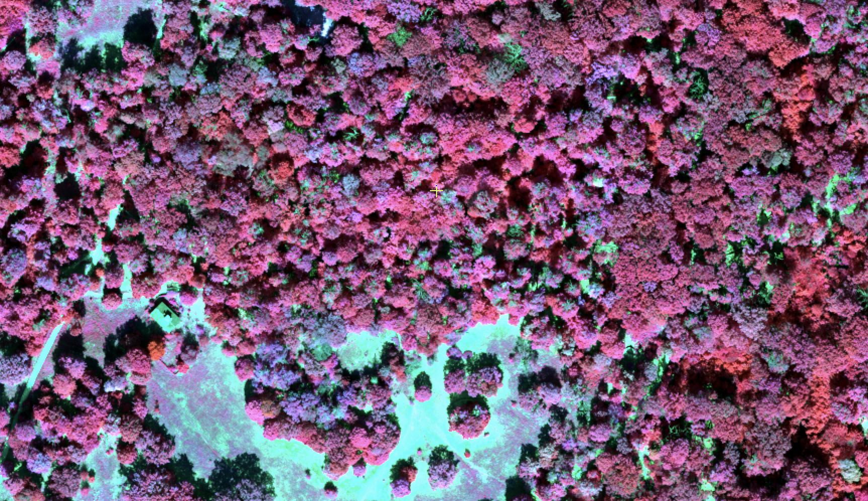
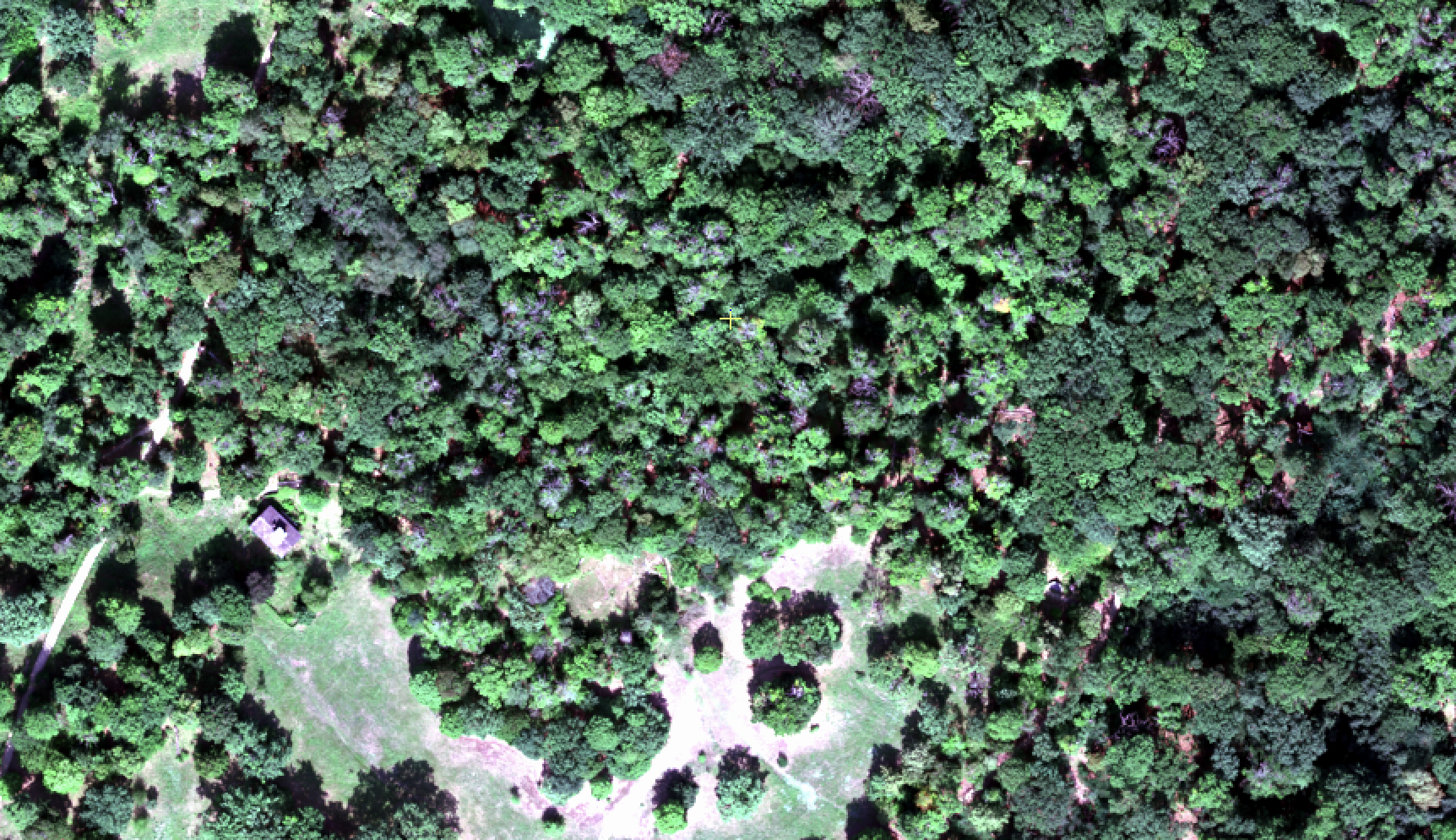
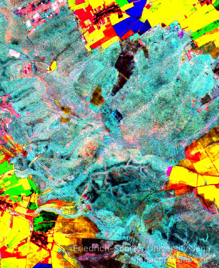
Fig. 7: Altum-PT true ortho multispectral data mosaic (above: Color Infrared RGB – NIR/Red/Green, below: true color RGB – Red/Green/Blue), flight altitude: 120m
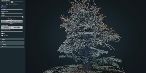
Most of the information about how to handle the Altum-PT data is documented in the Micasense Knowledgebase. The UserGuide also explains in detail the functionality of the Web configuration page that you access by Wifi. The mission input and the estimated mission results are very useful sub pages. Here you get a feeling for the card space that you need for different flight configurations and file types. This flight planning can later be used to program everything in DJIs Pilot 2 App but here you can already see if your plan will fit on your card space. Something that the Pilot 2 App will not do for you. I tested different configuration here and then finally after some flights settled with a flight configuration for my forested surfaces that will work well for 120m AGL and with GSD that I found acceptable. Metashape also supports pan fusion with the panchromatic band of the Altum-PT. Since the multispectral bands and the panchromatic camera is not a wide angle camera – it is approximately at 45 mm full frame equivalent, the resulting point cloud dataset is hardly showing 3D information. This can be a bit restricting when you want to combine thermal measurements within the 3D structure of the canopy. Fusion with LiDAR data helps but the thermal measurement clearly is lacking the 3D properties of the LiDAR point cloud and this cannot be changed in post processing – the thermal measurements from below canopy structure or leaf elements are just missing.